Understanding the Structural Forms of Steel Utility Poles
When it comes to modern power transmission and urban distribution networks, steel utility poles have become a preferred choice due to their aesthetics and structural efficiency. But what exactly goes into their design? Let’s break down the three key structural elements: the pole body, connection methods, and cross-arm types.
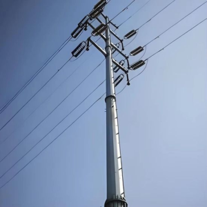
1. Pole Body Shapes: Balancing Aesthetics and Engineering
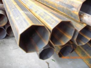
The cross-section of a steel pole typically comes in two main varieties: circular and polygonal. While circular sections exist, the industry standard has largely shifted towards polygonal shapes—most commonly regular octagonal (8-sided), dodecagonal (12-sided), and hexadecagonal (16-sided) sections.
Why polygons? It is not just about visual appeal. These multi-sided designs offer a streamlined look that blends well into urban environments while maintaining excellent structural integrity and ease of manufacturing.
💡 Pro Tip: The polygonal design also facilitates easier transportation and on-site handling compared to purely round pipes.
2. Connection Methods: Why Flanges Win
The way pole sections are joined is critical for stability and installation speed. There are three primary methods:
- Welded Joints: This method involves welding sections together on-site. However, it is generally not recommended because field welding quality is difficult to control and inspect thoroughly.
- Slip (Telescoping) Joints: This involves inserting one section into another. Experience shows that slip joints can lead to uneven deformation and excessive deflection (bending) at the connection point over time. Thus, this is also not recommended for critical structures.
- Flanged Joints: This is the highly recommended industry standard. Flange connections eliminate the deformation issues seen in slip joints and the quality risks of field welding. Furthermore, from a material cost perspective, flanged towers often require less total steel weight compared to other methods when calculating net weight, making them both structurally superior and cost-effective.
3. Cross-Arm Configurations
The cross-arms (the “arms” that hold the power lines) are categorized by their profile and cross-section:
- By Profile: They are generally designed as either Straight-type or Curved-type (often referred to as “Swallow-wing” or “V-shape” for their aesthetic and functional clearance).
- By Section: They come in Tubular (round) or Non-tubular forms, with the Box-type cross-arm being the most widely adopted non-tubular design due to its high strength-to-weight ratio.